German: https://mark-evertz.medium.com/diy-acoustic-booth-3dff20a380b3
Here we go …
Practicing, mixing tracks and listen to music until it rattles — whenever I like. Traveling through half the city to the rehearsal room to spare the nerves of my roommates and is no longer the preferred option. To indulge in the self-made noise to your heart’s content would be a thing. At this stage someone usually raises the question about headphones: “Yes, no but …” I need a soundproof cabin! PERIOD.
Egg carton and carpets are not enough. A room-in-room construction that largely keeps my sound events away from the outside world should increase my quality of life.
After thinking probably 100 times back and forth whether I should buy a finished product (e.g. http://www.studiobox.de => sack expensive!), building by myself, or let it go and continue to complain, I decided to do it myself try (Yippiejaja). Problem: My craft experience is close to zero.
Various online forums have given me courage and inspiration. Finally, at the end of December 2019, this colleague (Callisto) DIY — Drum Cabin convinced me of the feasibility. Without information from the digital world, I would be stuck.
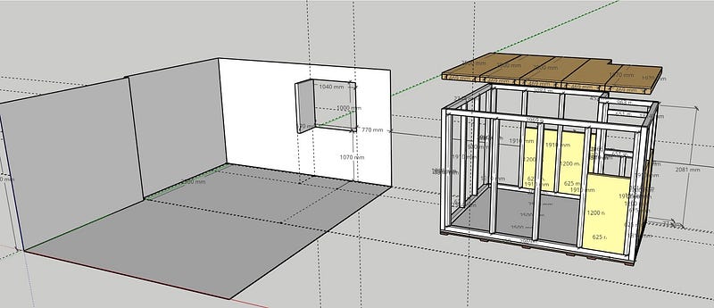
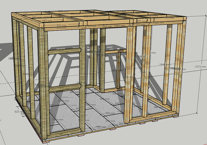
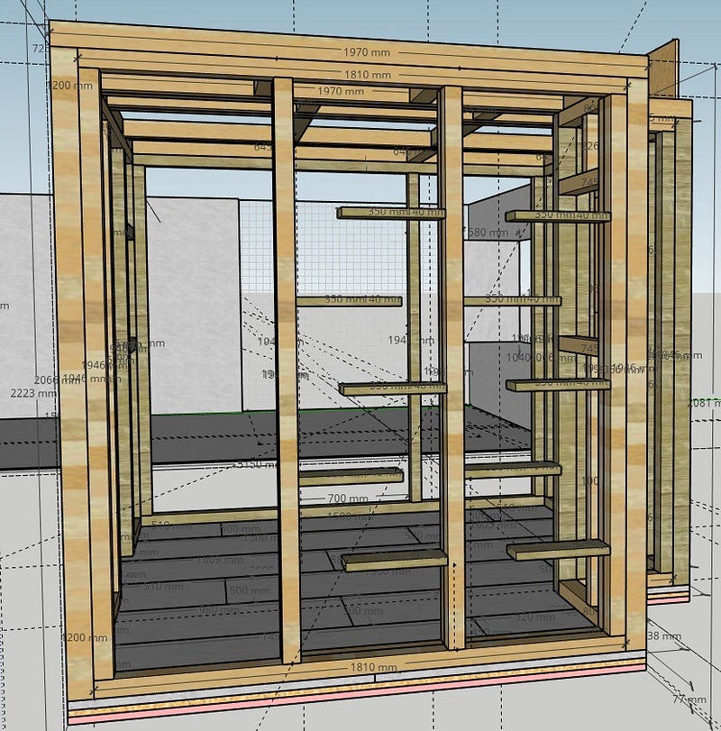
Virtual walking tests with the help of http://www.sketchup.com gave me first impressions of the construction and materials (as well as quantity and weight). In fact, it was necessary to do some project planning: Ordering stuff indiscriminately that I can’t store or have no space to work afterwards would not be expedient 🙂
I also had to think about the construction in advance. First the side walls and then the ceiling, or the ceiling in modules and after erecting the walls, pushing the ceiling from the side on top (how much space do I need to change something on the ceiling from above?)? Questions after questions 🙂
The Room
In addition to my apartment, I have rented a craft room that is supposed to serve me as a studio. However, I never feel completely free in it. The concern that my fellow human beings potentially listen to my strumming reluctantly influences my game. The room is currently home to various devices, along with guitars, cables, stands, etc., and serves more as a warehouse. That should change.
Since the room is rented, I don’t want to make any structural changes. I also have to consider the weight of the construction, since the room is not on the lowest level of the house — it is not standing on the ground. Common building standards are around 1.5–2 kn / m2 (roughly translates to 150–200 kg / m2).
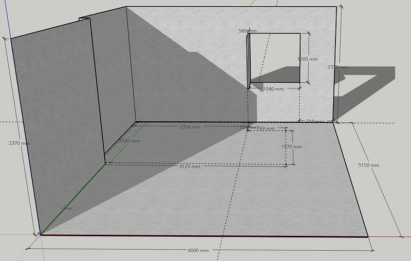
The dimensions of the floor space result from a compromise between requirements, weight, difficulty of construction and conditions of the room (windows, varying ceiling heights, etc.). After all, I have about reasonable 7.5m2 (external dimensions) to make noise. The 7.5m2 allow me about 1125–1500 kg / m2 payload to build the cabin.
The knowledgeable observer does not overlook the fact that I ignore the no parallel sidewall principle. Optimal room acoustics is not priority 1 in my case. I preferred a simpler construction and will measure and treat the room acoustically later.

Basics
The floor of the cabin is constructed in three layers:

The bottom layer consists of 6 strips of polyurethane plastic — Sylomer (2500mm, 25mm, 125mm). It serves to decouple the construction from vibration. The sound cabin “floats” on this rubber mounting and uses a mass-spring system, as used in railway technology, to prevent sound events in the cabin from resonating in the rest of the world. The rubber strips are the only points of contact between the cabin and the outside world.

Sylomer is produced in different variants, as required with regard to damping and load. It is manufactured by RRG in Germany and can be ordered here: https://www.baubedarf-spezialartikel.de/. I use the standard strips: Sylomer SR 18, 0.018 N / mm² 25 mm. 0.018 N / mm² corresponds to approximately 1800kg / m2… should be enough.
I filled the space between the Sylomer strips with 40mm mineral wool (not shown in the model). The weight of the upper layers compresses the wool so that the cabin lies on the rubber strip at the end.

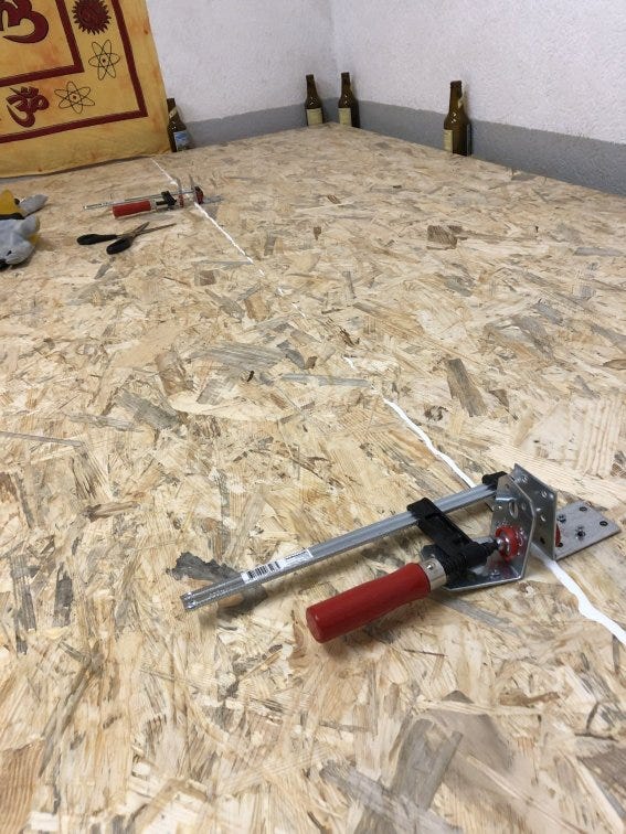
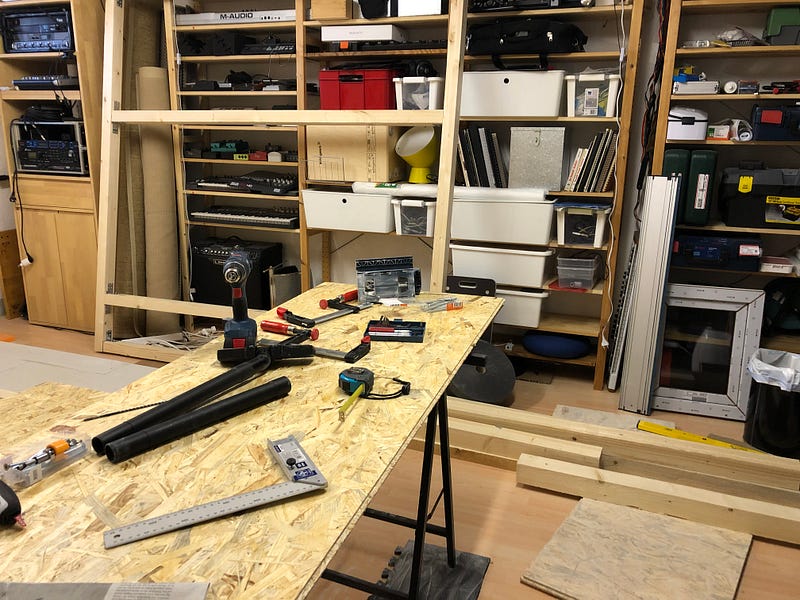
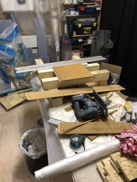
I used five 22mm thick, 650mm wide and 2500mm long OSB 3 chipboards for the base plate. Four plates lie across, one in length (right) on the Sylomer strip.

The panels are glued together on tongue and groove. For the contact pressure, I screwed angle connectors onto the plates and pushed them together using screw clamps.
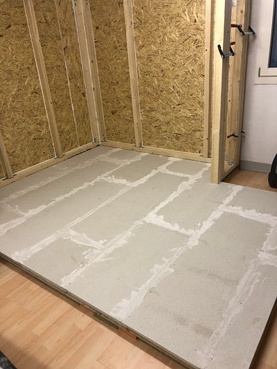
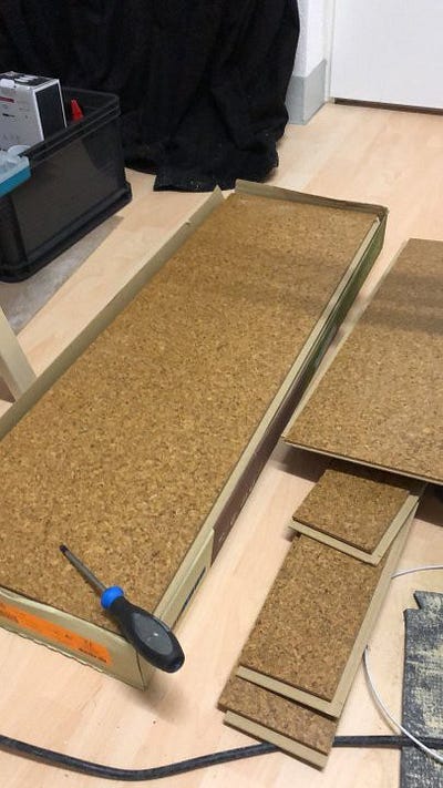
The third, mass-bringing layer, consists of Fermacell screed elements with an additional 10mm rock wool layer (no idea whether that will bring what?).

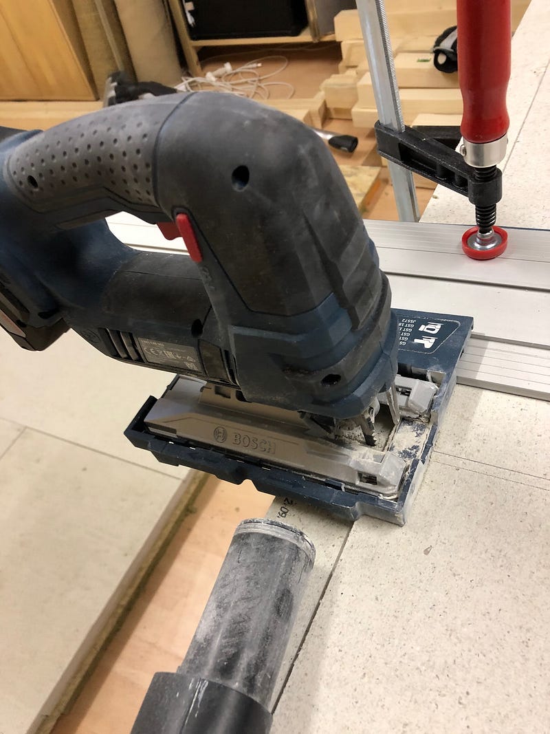
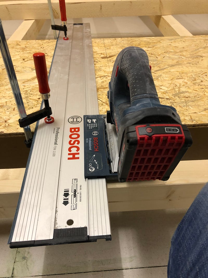
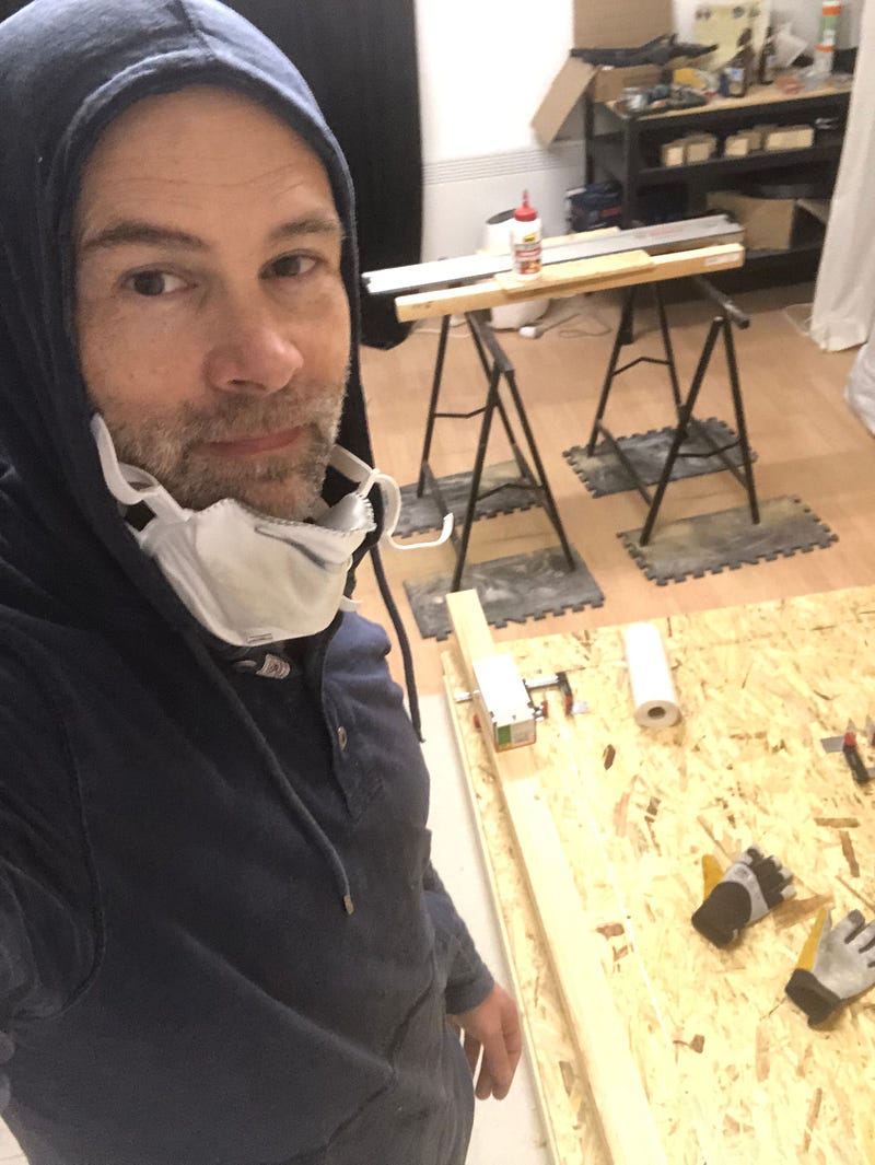
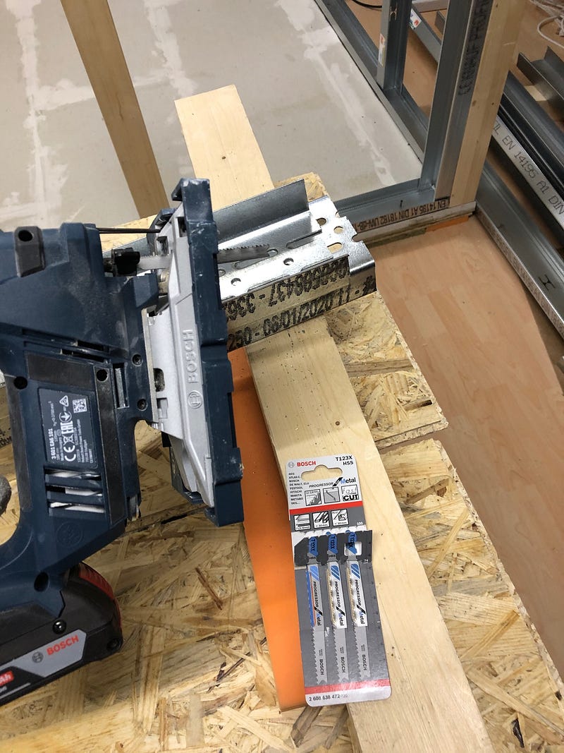
The screed elements are laid fluently and must be sawn accordingly. This is quite a mess (respiratory protection!), Which has brought my vacuum cleaner beyond: — |.
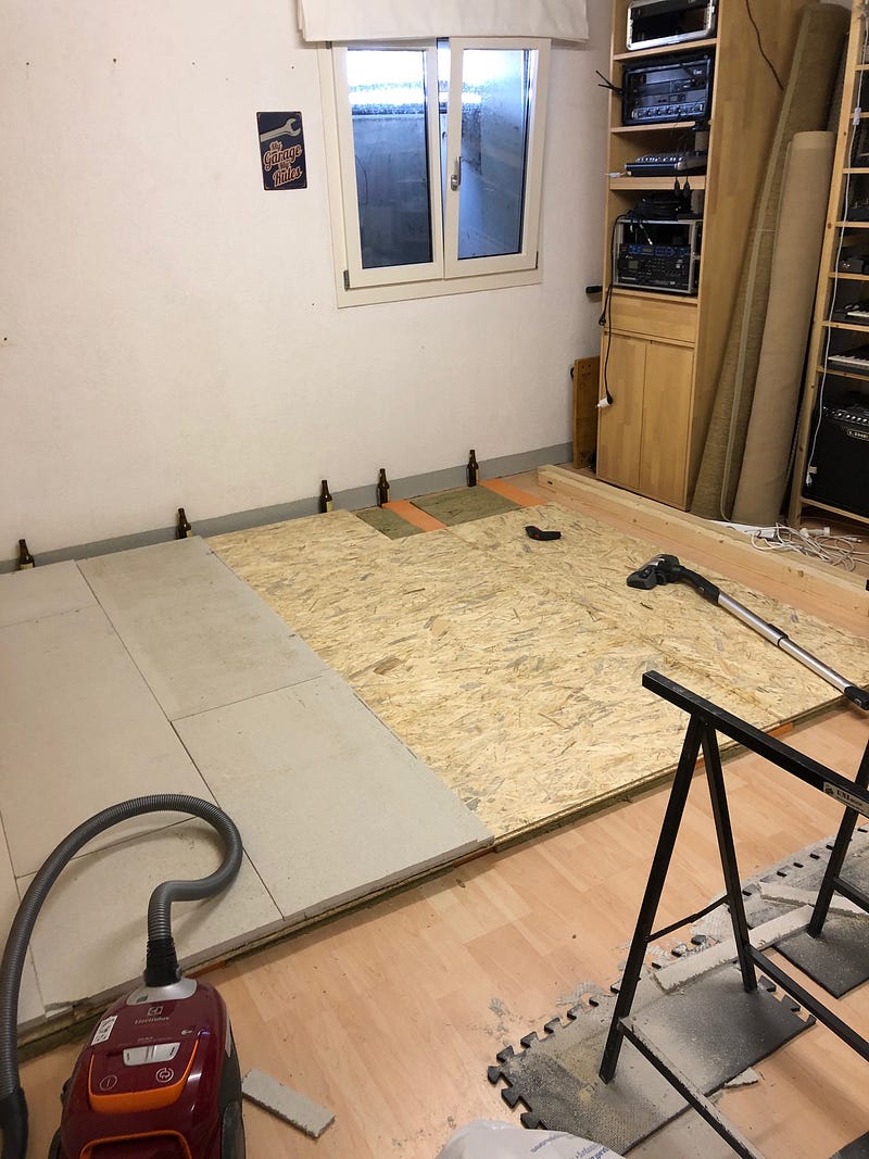
Attention: Before ordering the plates you have to take the exact dimensions into account. The plates are specified with 1550mm x 550mm. However, they are laid 50mm overlapping. The 50mm fold of the panels on the outer edges is sawn off. This means that the panels are only 1500mm x 500mm in size. I had ordered one panel in addition— I was lucky!
The saw blade is a somewhat coarser but normal blade for woodcuts. I can highly recommend a guide rail as used for circular saws. With an additional adapter for my jigsaw, it worked great. The joyful excitement about my newly acquired skills would have made my sawing edges artful without this utensil, but guaranteed not to be straight.
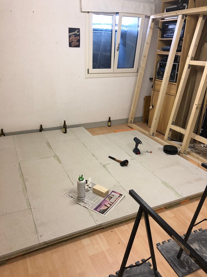
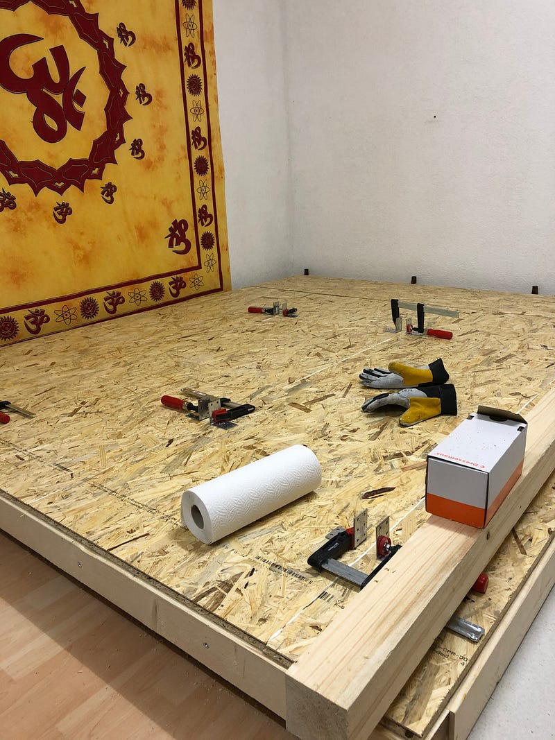
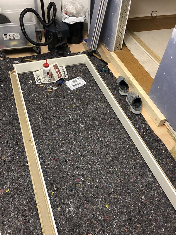
To ensure that the panels close well and no longer slip, they are glued with a special adhesive and fixed with quick-assembly screws. The latter prevents the hardening adhesive from pushing up the panels.

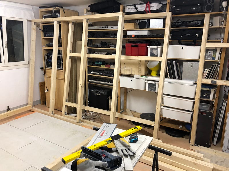
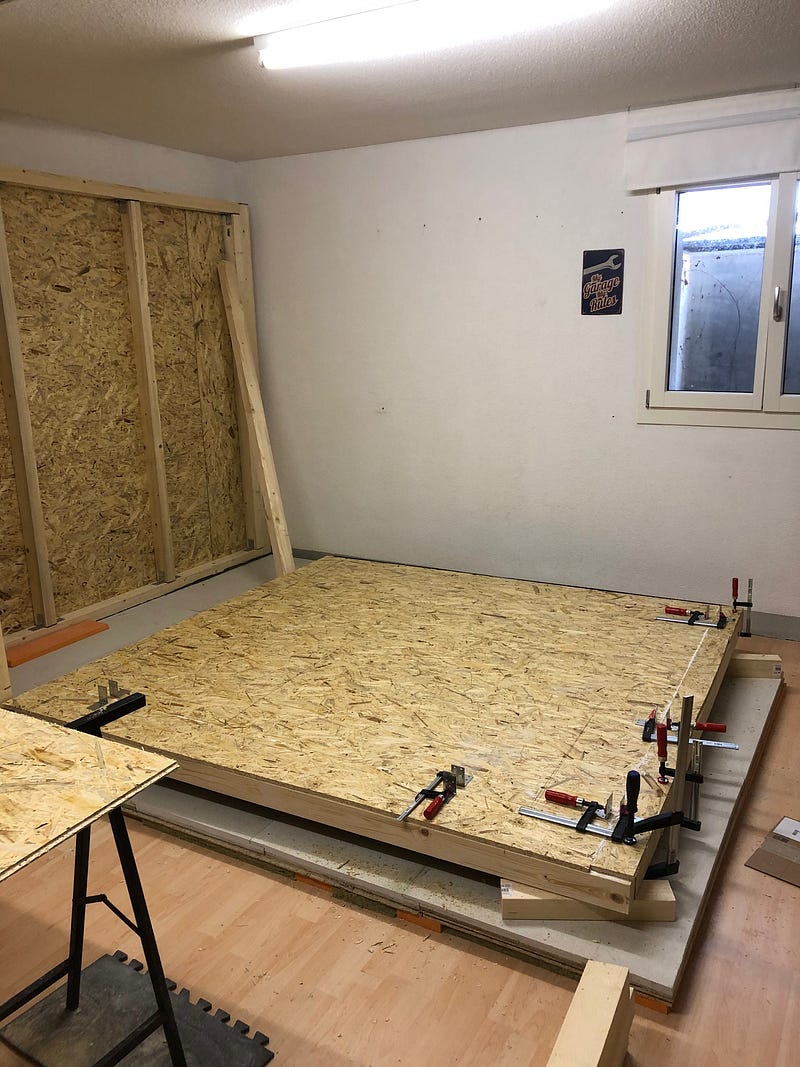
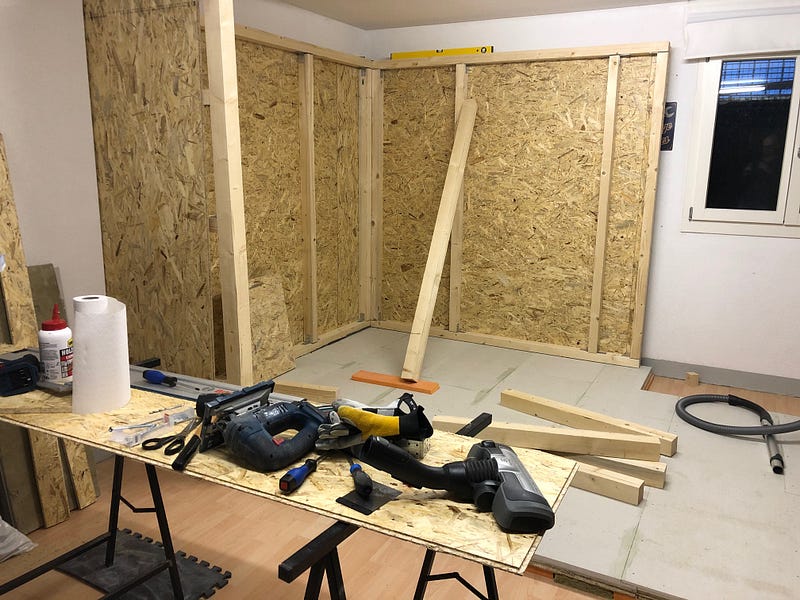
Finally: The finished laid, glued and screwed base plate. On the right you can already see the wooden frames for the first side wall.
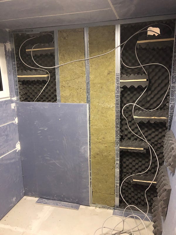
Construction of Walls
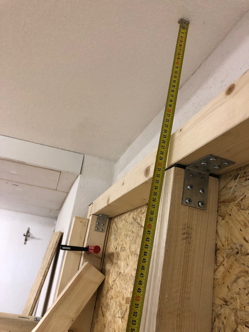
The structure of the sound cabin is constructed as a wooden stud frame. The frames of the walls consist of 60mm x 80mm squared timbers, which are screwed to 80mm x 80mm corner posts (6 of them). I use the less thick squared timber for the frames to save some weight.
I ordered the beams for the side walls online (Hornbach) and had them cut to size. Various opinions can be found in various forums. Some have had good and bad experiences regarding the quality of the wood and the accuracy of the sawing work and therefore recommend selecting the beams in the hardware store yourself and sawing them yourself. My experiences are thoroughly positive. The cut is accurate to the millimeter as ordered and no bar was crooked or of unsatisfactory quality. The time saved by the already sawn timber is considerable. In addition, you reduce the noise pollution of the environment (unless you have a soundproofed room in which you make noise …).

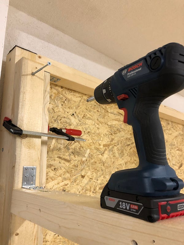
The woods are connected via metal angle connectors and 3.5x40mm screws (pan head). Anyone tell me why 90% of all screws are countersunk screws? What a shit solution if you want to use them with angle connectors!
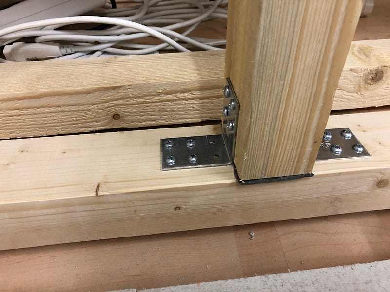
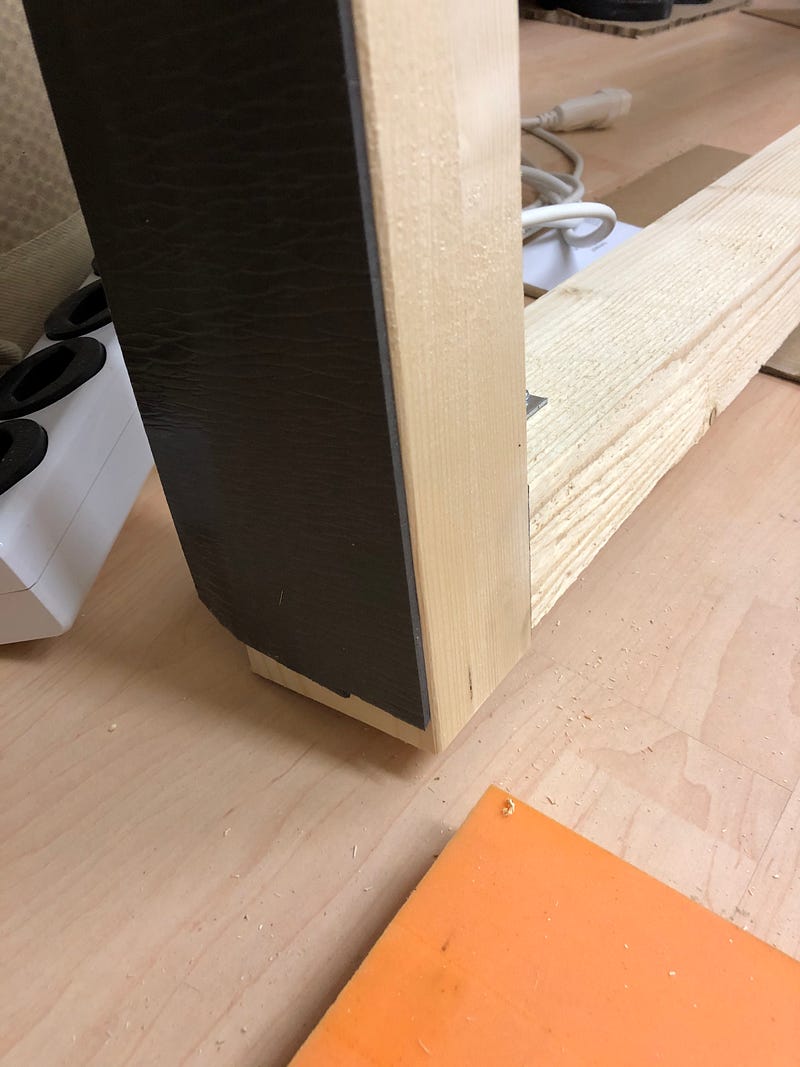
I glued all the posts and struts with sealing strips at their vertical contact points. This also applies to horizontal beams in contact with the Fermacell panels. I hope that this will result in less wood-on-wood creaking and secondly an additional acoustic decoupling (look here). Incidentally, the scaffolding is not screwed or glued to the floor.
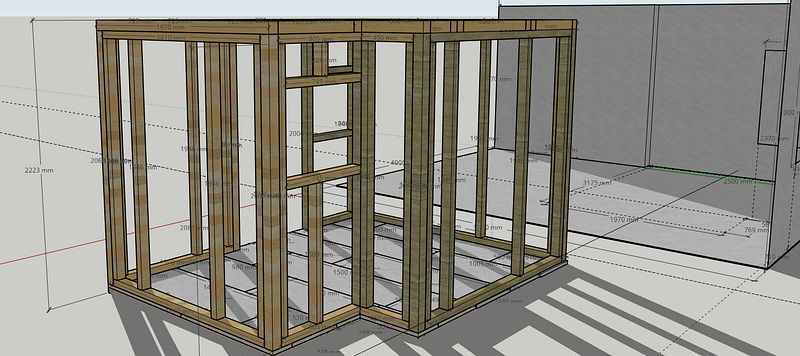
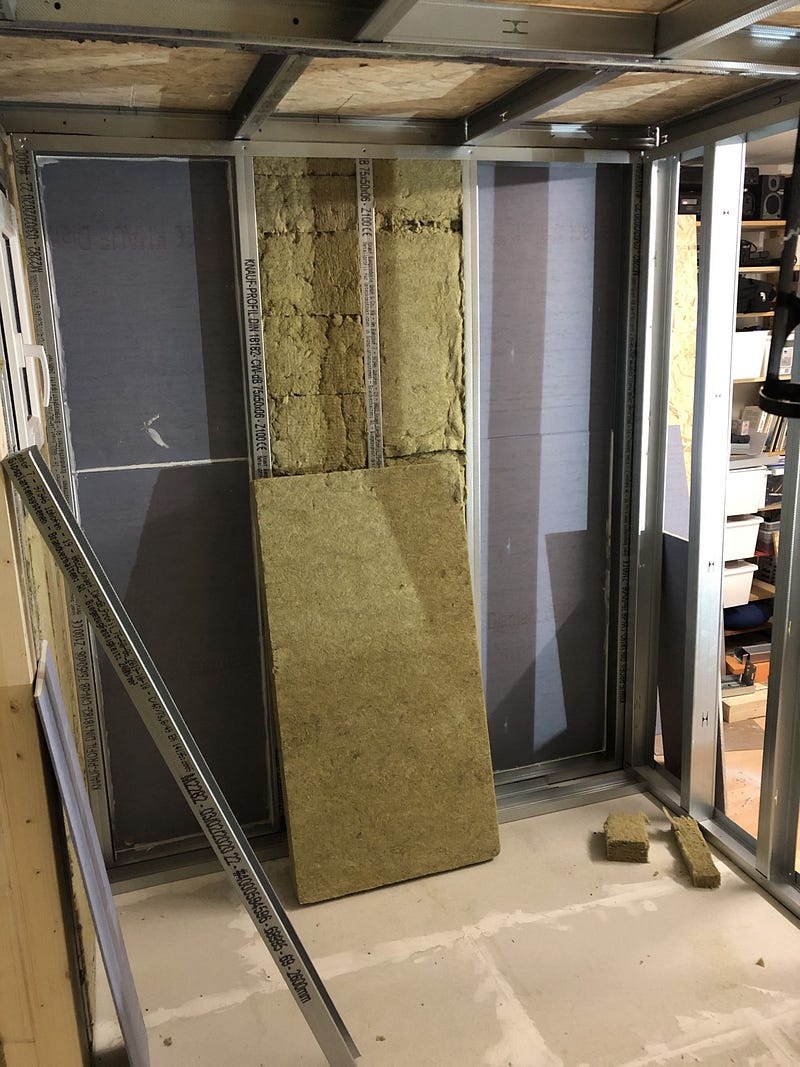
I carried out the planking of the walls that are close to the outer walls while lying down (so not me, of course …). I used OSB 3 boards 625x2050x15. I would have preferred 22mm plates, but I had to keep an eye on the total weight. If the degree of absorption is not sufficient, I will make the interior paneling correspondingly stronger.

The panels are glued on tongue and groove and, as before, pressed together on the floor with angle connectors and clamps. I then fixed the plates with 5x40mm countersunk Torx screws — no further glueing of the boards to the beams.
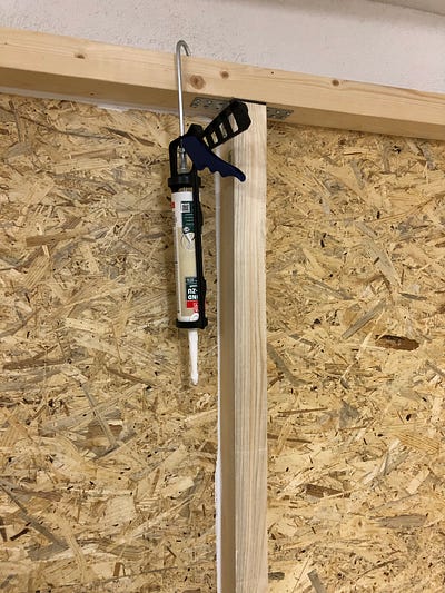
So that there are no joints and audio snippets do not find a way out, I will later seal all connection points (boards / beams, beams / floor, beams / beams) with acrylic.
The walls are connected to each other via corner posts and 6x12mm countersunk screws. Nothing works here without pre-drilling. First I pre-drilled about 30–40mm with a 3mm drill with milling for the countersunk head, then I widened the hole about 50–60mm deep with a 4mm drill and then pre-drilled almost the entire screw length with a 3mm extra long drill. Wood drilling is developing into a real passion.

As a final step before I build more walls, the joints in the walls and the floor slabs still need to be sealed. I use acrylic sealant for the panels and beams of the walls, and Moltofill depth filler for the floor panels. Professionals recommend special drywall filler, but you can see from the generosity with which I spread the spatula that I am not a professional 😉

Paradigm Shift
When I mentioned my sympathy for craftsmen with wood in the introduction, I was looking for another justification: namely the supposedly better property of sound absorption from wooden stud walls. However, I recognized the misconception after consulting my favorite book on the subject (table on page 37). Drywall stud frames with metal profiles and plasterboard cladding do a much better job with regard to absorption.
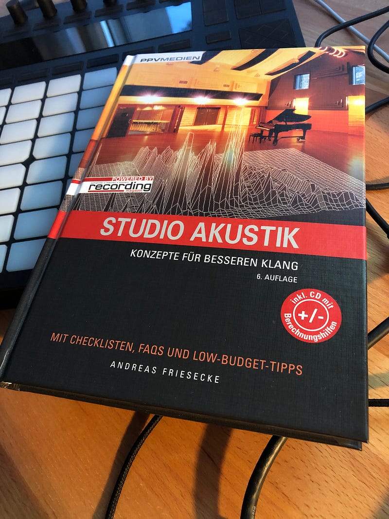
Since metal profiles weigh up to 1/4 of the weight of the square timbers used in my case, the saved weight can be invested in additional formwork (more / thicker panels). Cool thing!
However, the different material / system requires different tools and different work steps. Fumbling around is the order of the day and it goes more slowly.
… I still like working with wood 🙂

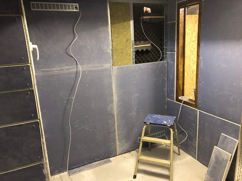
Window-rizing
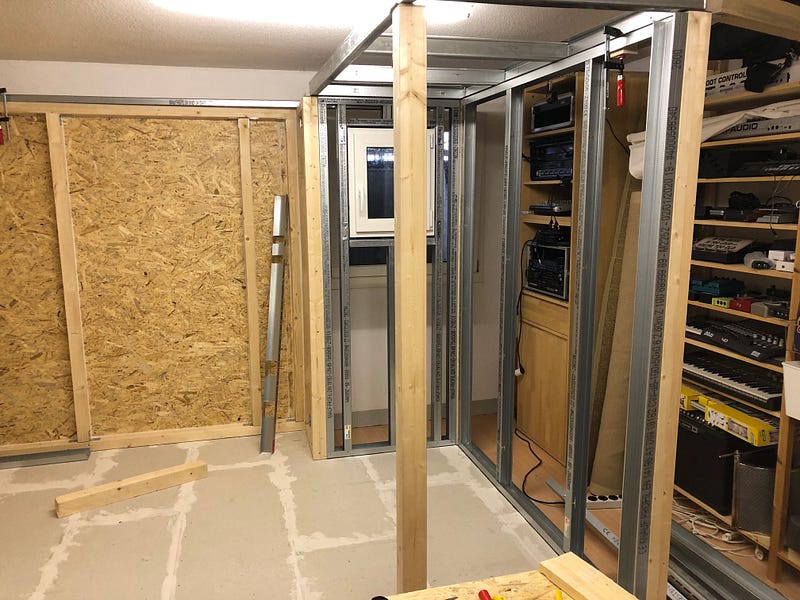
My first attempts using metal profiles are promising. Gradually I get into the groove of the cutting, bending, sawing and crimping is done faster. What makes me a little queasy is that free-standing walls made of metal profiles are initially less stable and often have to be temporarily fixed during assembly. Overall, it appears that the finished box will not be suitable for playing football or similar in it — nothing is further from me 🙂
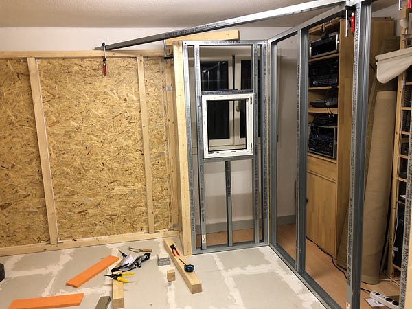
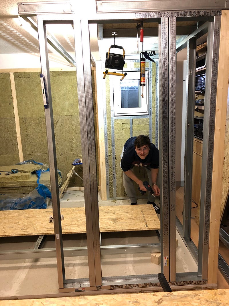
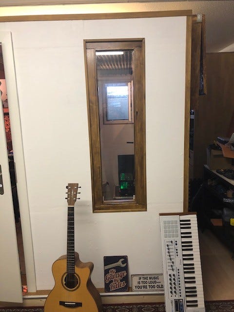
Since I am waiting for more material, I started the installation of the first window.
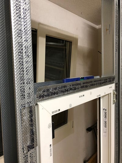
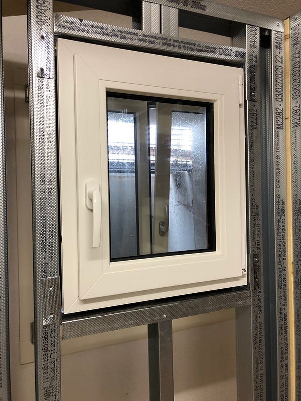
The window that needs to be installed is a triple-glazed 500x600mm prefabricated window from the hardware store. On the one hand, it is supposed to counteract a psychological-negative “jail feeling” and, moreover, to allow access to the outside window. The box is designed so that I can walk around the outside, but that’s not exactly what I always want.
First I put two CW profiles in the window width (+ approx. 5mm air left and right) in the frame. A 2mm UA profile in the middle under the window opening carries the weight. A UW profile, with an excess length of 10 cm left and right and crimped with the CW profiles, forms the lower frame of the opening. Incidentally, the UA profile is not screwed to the floor, but only set with corner connectors (or post brackets). Nothing slips there!
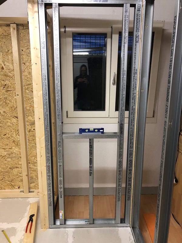
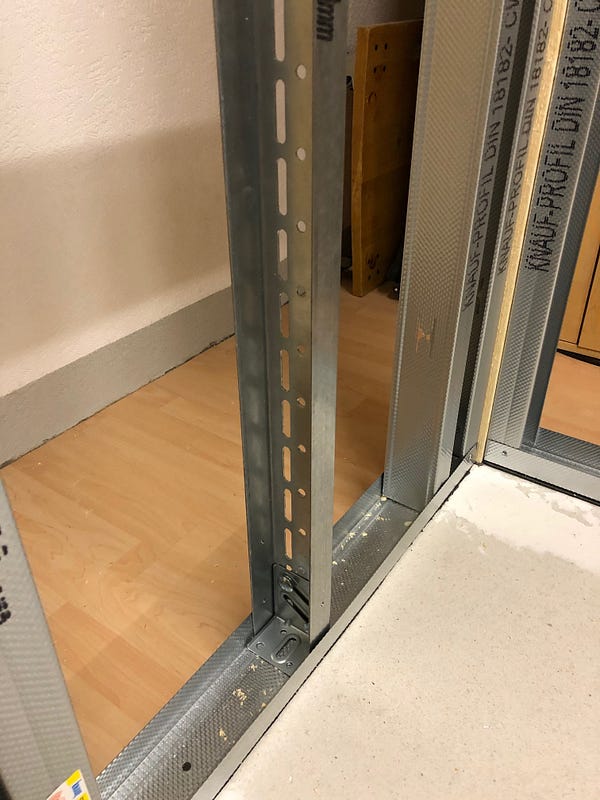

Like the lower frame, the lintel is cut from a UW profile that overlaps 10cm on both sides. In fact, I sawed a longer UA profile later because the window was a little too low for me.

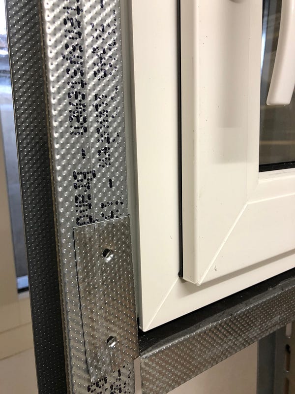
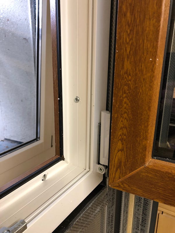
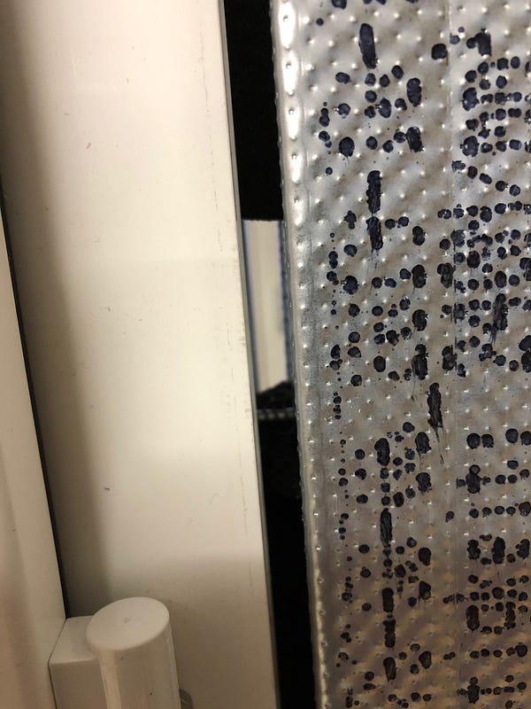
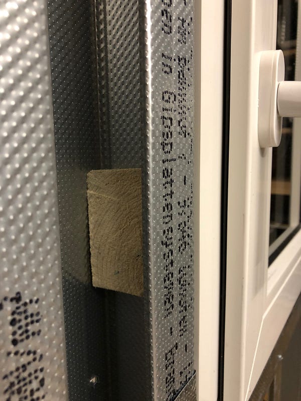
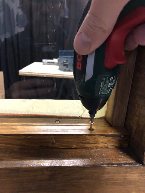
I used sealing tapes to fix the window. Once glued from the roll and onto the window frame, the material massively increases in volume, presses the window frame against the metal profiles and thus stays in position. So that the window cannot be pushed through the profile wall, I drilled two holes through the frame on each side and screwed it to the metal profiles with wood screws. So that the screws grip better, I added wooden blocks.

The only disadvantage is the 100% increased area for window cleaning : -|

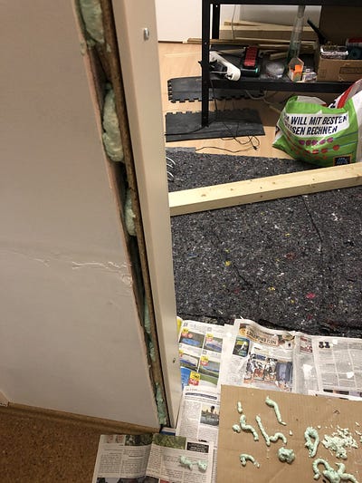
Finally, the windows are firmly connected to the frame with two-component assembly foam. So as not to waste too much of the less environmentally friendly construction foam, I won’t do this before installing the second window and the door.
Profiling
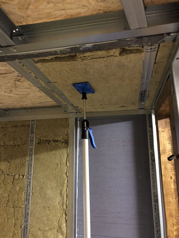
A real difference to working with wood is that the unplanked metal profile walls are initially much less stable and have to be temporarily supported more often. Gazelle-like sneaking on my part is necessary so that the whole clutter does not collapse during assembly (yes, I know you should actually do it in pairs).
Incidentally, the 2mm stiffening profiles (UA) can no longer really be processed with tin snips. With a hacksaw by hand, or appropriate blades for a jigsaw, it works (nice and slow), but quite well.
The front wall, which is supposed to house a fire or soundproof door and another window, is constructed with 100mm profiles (in contrast to the 75mm profiles of the ceiling and the other walls).

Modular ceiling design
Since I am no longer the youngest and I have less to oppose gravity than before, I planned the ceiling in modules … Well, that’s partially right. The modular structure is absolutely necessary for reasons of space, and the height of the outside space does not allow me to plank the ceiling from above. A previously completely assembled ceiling plus planking will then actually be far too heavy and very difficult to assemble.
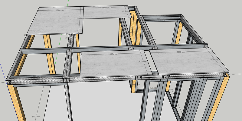
The modules are constructed from UW profiles in the longitudinal and CW profiles in the transverse direction (the sketch above is inaccurate). The cutting, bending, screwing, crimping of the metal profiles is progressing slowly — more steps must also be taken into account when constructing ceilings, window cutouts etc. Translated: I have to inspect my work more often, scratch my head, or make more mistakes — which is particularly stupid if I screw up a profile and have to wait for a repeat order. I would have been faster with wood, but the weight savings are considerable and with more routine building with metal profiles will probably have a tempo advantage.

The formwork consists of the same 22mm OSB panels as the floor and is screwed to the profiles with drywall screws. Sometimes the screws do not pull the profiles completely onto the wooden panels and push them away a little. I will later seal these gaps with acrylic.
It is not easy to work with profiles precisely. Despite the greatest care, small deviations have arisen. Some of the ceiling modules are 2–3mm crooked and protrude slightly. I hope to compensate for this with the external formwork, without any negative effects on the insulation.
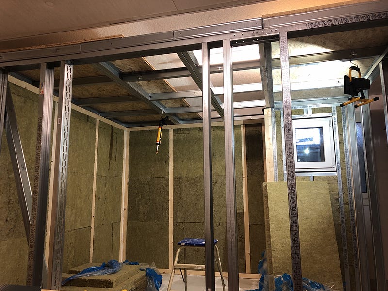
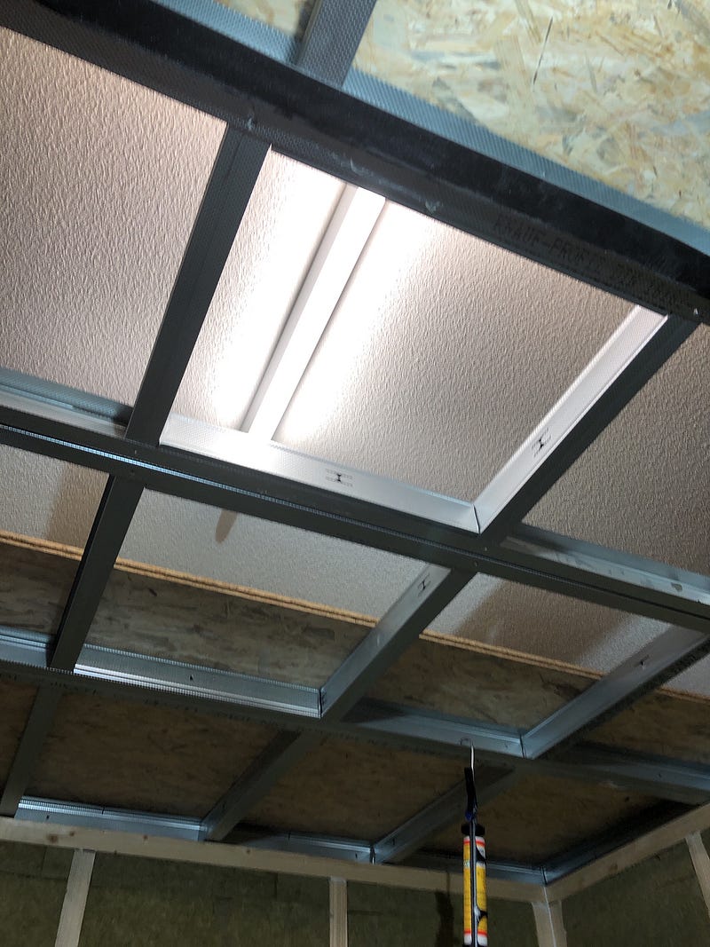
How do I get the ceiling light in the outdoor area if I need to replace it? Inspection hatch, skylight … I have to come up with something else. At least I have provided two cutouts and made a kind of frame with CW profiles filled with mineral wool.
Refreshing
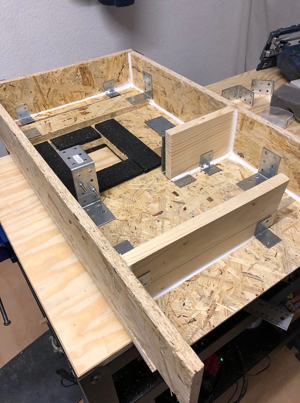
Occasional breathing should benefit from the continuous supply of fresh air. So that this takes place without interrupting the musical activity, soundproof ventilation is required. Somehow, air has to be constantly drawn in and out of the cabin without the sound escaping. The idea that I stole from the aforementioned forum is based on a vertical extension of the ventilation duct.
The construction consists of two shafts: on the left, warm air is drawn out of the cabin from below through a labyrinth, and on the right, fresh air is drawn in in the opposite direction.
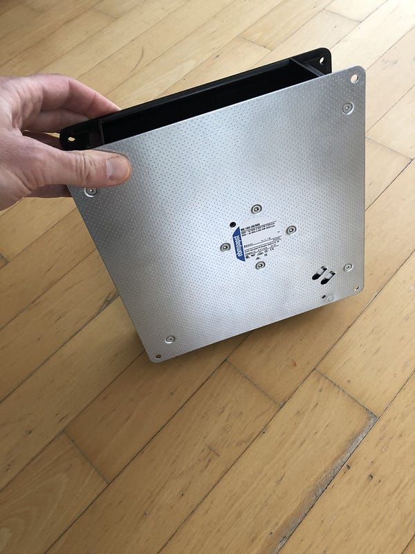
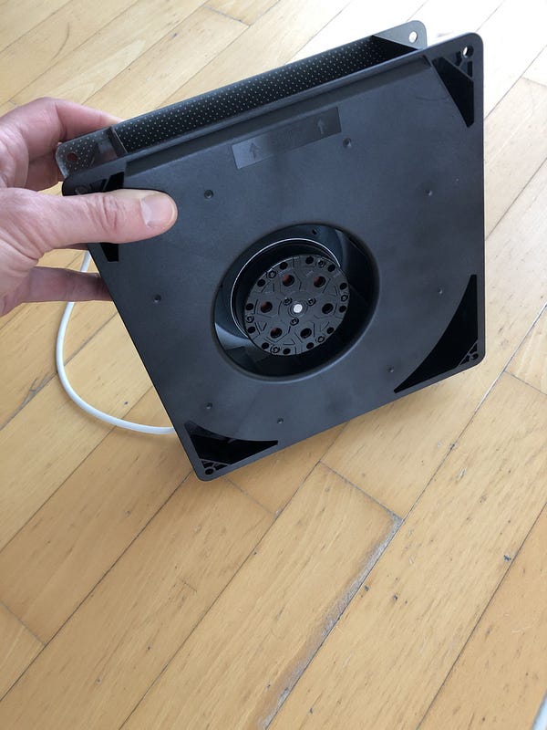
So that something really moves there, the air is sucked out by a radial fan at the top left (outside). The ebmpapst RG 160–28 / 56S fan model runs with max. 2750 rpm and exchanges 202m³ of air per hour. If I ignore the resistance of the labyrinth, the indoor air (approx. 12m³) would be renewed in less than 4 minutes.
The actual construction differs somewhat from the model. I did not place the two shafts directly next to each other. From the inside perspective, the air discharge will now be seen on the right and the supply on the left.
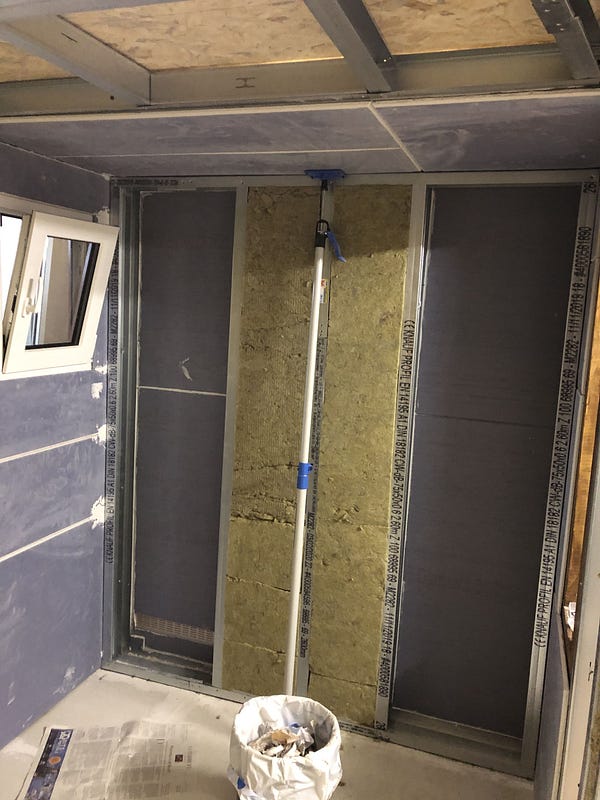
In order to achieve a sufficiently large cross-section for the volume flow, I built a frame from two 75mm two profiles in a row. To do this, I first had to plank this part of the ceiling.
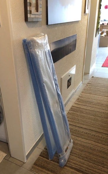
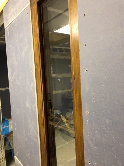
On the right you can already see the glazed wooden frame for my window brand homemade.

The wooden boards are attached to the gypsum fiber boards with metal brackets and clamped in the profiles. I stapled the bubble foam. With the formwork from the inside, I have to wait for the next delivery of further gypsum fibreboards.


The interior cladding is a bit fiddly: The cutouts for the ventilation grilles have to be milled and sawn, and the dimpled foam for the gaps between the boards cutted and stapled.


I led power cables from the outside through the ventilation grilles. For this I broke sticks out of the ventilation grilles and put the cables in there over the labyrinth. Actually, drywall profiles made of metal allow cables to be laid quite easily directly in the wall. With my mix, however, a wooden beam gets in the way at the end of each wall. That’s why I decided to avoid major dislocations and to lay all cables inside the box using self-adhesive cable ducts. In addition, I do not have to drill any further holes in the panels that endanger the insulation properties.
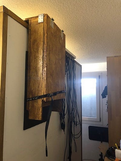
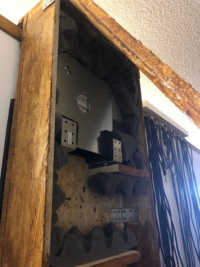
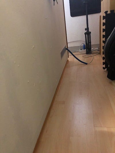
For better maintenance options, I installed the fan on the outside of the cabin and donated a box with a labyrinth. If the fan is still too loud, I will expand the maze. Incidentally, the box is not permanently connected to the cabin. The top of the box is a board that is about 20 cm on the ceiling. The box hangs at the side of the soundproof cabin. The fan and the cabin are mounted on foam rubber so that no vibrations are transmitted to the cabin. From a previous project, I still had remains of fitness mats, which I also placed under the box (top and side). They make a wonderful contribution to decoupling!

Last but not least, I gave the fan a speed controller. It remains to be seen whether I really use it in operation or whether I let the fan run mostly at full speed. Incidentally, the speed controller from ebmpapst REE10 was not that easy to get. I finally found him online in England. If you are interested, I can look again at which provider.

The finished fan housing has gotten a cover. “Rustikal oak” subtly blends in with the rest of the vintage flair of my cabin 🙂. The somewhat strange looking recess at the lower end of the case was made because I didn’t have enough wood for a longer cover. I didn’t want to saw off the sides either. I wanted to stay flexible to extend the housing in case I need to further reduce noise emissions.

The Floor
In order to have it a bit more comfortable under my feet, I opted for a covering made of hard-wearing cork tiles. After laying / gluing a steam foil, I layered the tiles for 24 hours for acclimatization. The steam foil is probably superfluous in my case, but as a DIY newbie I just wanted to do it.
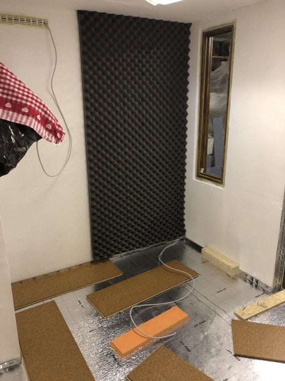

Cutting to size with a fine wood saw blade is easy — after a few hours all the tiles were laid.
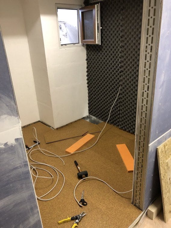
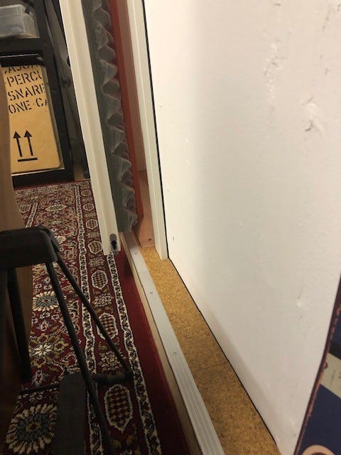
I used cork baseboards as finish off the wall. Since I didn’t want to drill any holes in the plasterboard, I attached the clips, that are usually used to hold the strips, with hot glue. That worked moderately well. In the end, I left out the majority of the clips and stuck the strips directly to the walls.


Window 2nd Edition …
Although I don’t need another window, but I created a small challenge in addition to the simple routine of construction, to satisfy my need for luxury. It should be self-made with optimized acoustic properties. Specifically: double glazing with an 8mm and a 12mm slanted pane.
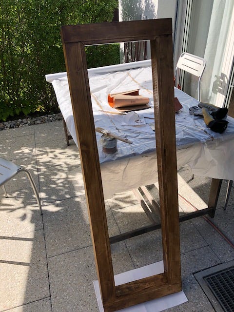
The frame construction consists of screwed 80x80mm square timber, which is supported by a UA profile in the metal frame.


I sawed the frame and bars angled to hold the panes in place and then painted them with wood varnish (luxury as I said).

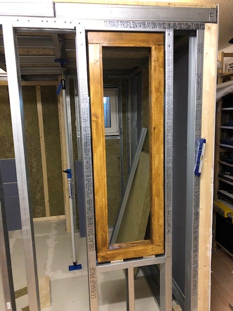
The wooden frame is screwed to the CW profiles and sealed with 2K cunstruction foam. On the occasion I also sealed the small window in the back.
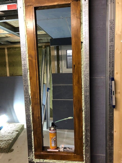
The first thinner 8mm pane is inserted and fixed with the profile strips. Of course, I had to pre-drill the screw holes in the thin wood. Incidentally, you cannot see the window seals (self-adhesive rubber P-profiles) that I glued to the wooden strips. Then brown acrylic helps so that no beeps really get through. Dark or brown acrylic, because a white seal would be reflected from the inside of the panes (I never thought about anything like this before this project (in my previous life) :-))).

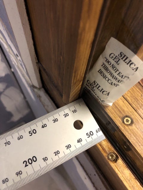
At the bottom it’s 15mm from the frame to the window and at the top just under 40mm. On a length of 1200mm there is a difference of 25mm. If Pythagoras wasn’t completely wrong, the angle is slightly less than 2 °.

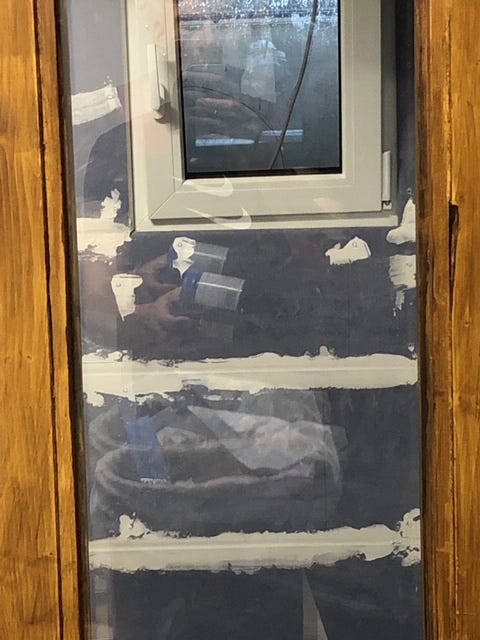
You can clearly see how the light breaks differently in the window (everything is reflected twice) — and so does the sound. With this construction, less resonance (aka standing waves) should be formed and flutter echoes should be avoided. We’ll see…
The Door
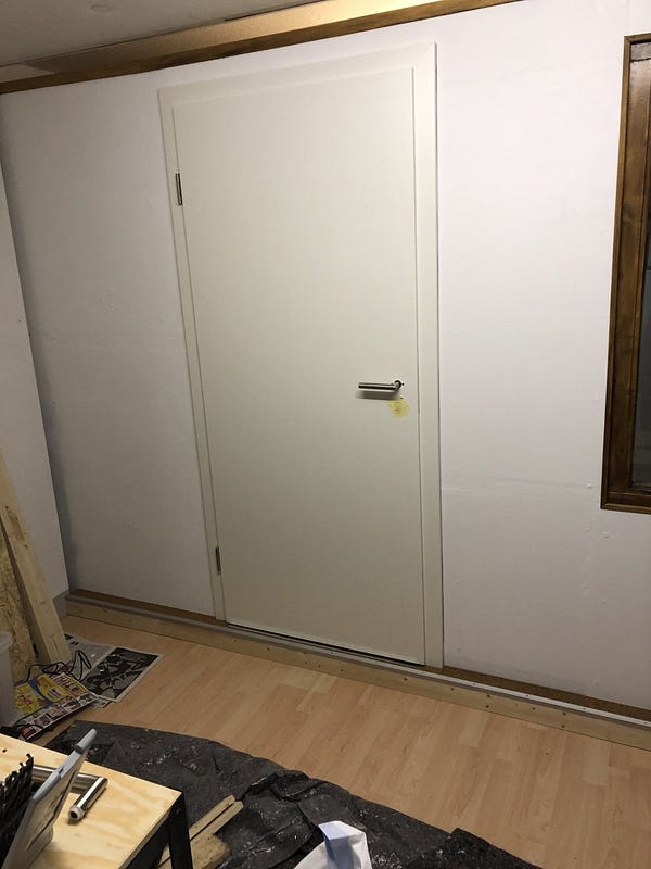
Doors, the weakest elements in terms of sound insulation, require special attention. 80 kg heavy and equipped with a retractable smoke protection, I had respect for the installation — nothing should go “wrong” in the truest sense. I ordered the door (soundproof door set white RAL 9010 CPL with surrounding frame — Interio, 37 db Rw, P — soundproofing class 2) in a set with the frame from www.deinetuer.ch. A damping level of 37 db Rw seemed to be sufficient for my purpose. More would have been possible, but then the door would have become more expensive and heavier.
But how do you fix a door frame that has to carry a bit more weight than usual into a free-standing drywall made of metal profiles? The reference in the assembly instructions to wall anchors is daunting. Since beauty is secondary, extra strong self-tapping screws are needed, which are drilled through the frame backed with wooden panels and screwed into the metal profiles. Afterwards, everything stays in place with foam.


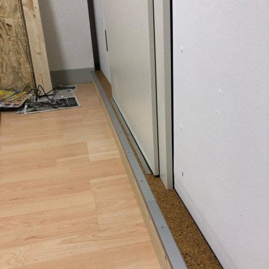
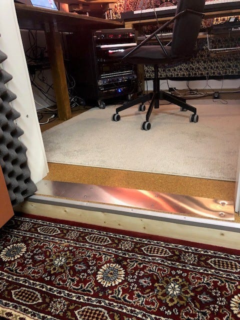
During assembly, I noticed that the door is sitting in the frame but protruding slightly. Seen from the side, she is sitting on the cabin wall. The door “floats” above the exterior floor. The retractable smoke protection hangs ineffectively in the air.

A (not planned) door threshold, which I extended across the entire width of the cabin for the sake of appearance, offers enough resistance for smoke protection and seals well. Remnants of the cork tiles, as well as aluminum profiles for stair nosings, also make the construction reasonably pretty. The threshold consists of two screwed 80×80 square timbers that only lie on the floor. A screwed metal plate connects the threshold to the cabin floor. Nothing wobbles there!

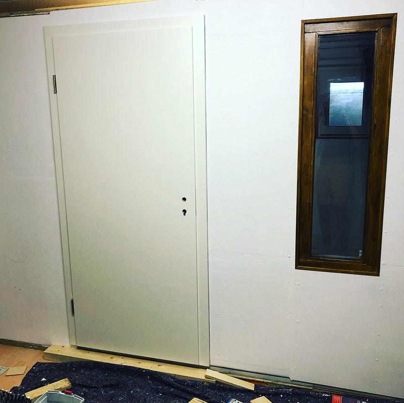
When closing, you notice a slight counter pressure — the room air is slightly compressed, which indicates good air and therefore sound insulation of the cabin, great! I filled the keyhole with plaster of paris and covered it with a piece of white cardboard (first seen in the pictures below).

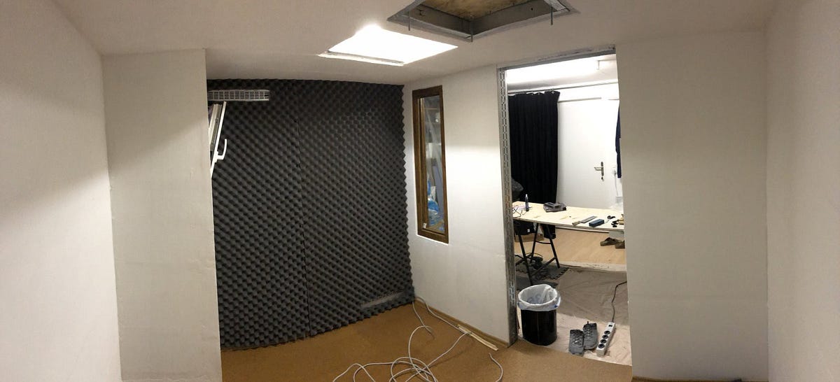
Finally …
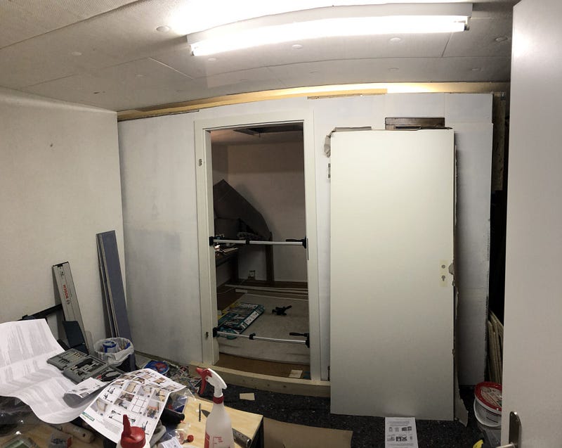
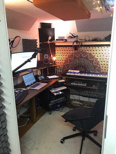
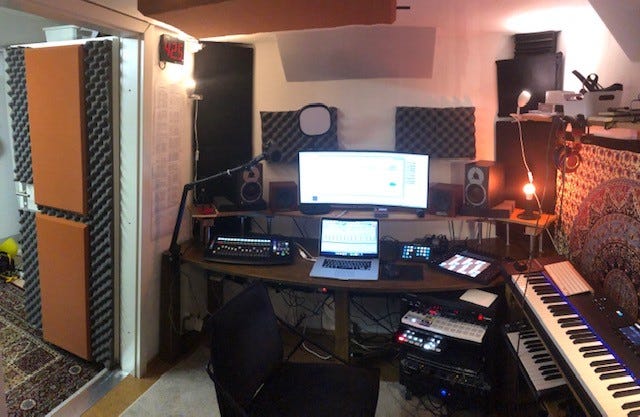
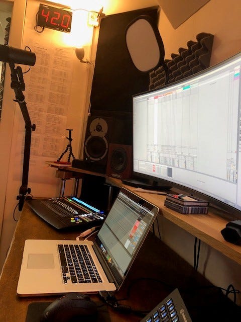
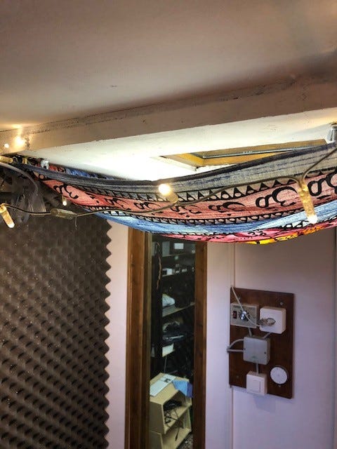
… some impressions of the completed cabine from outside …
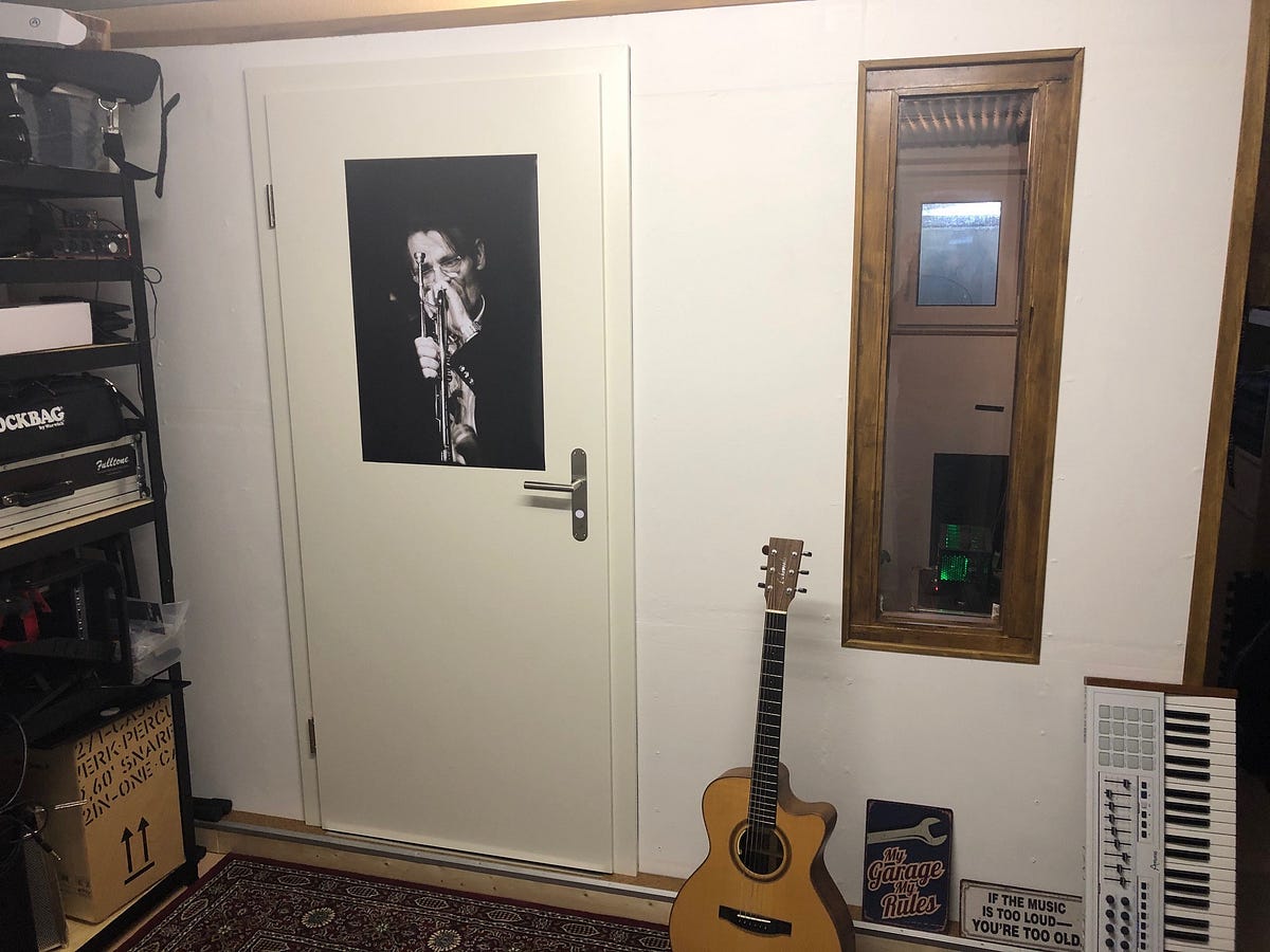
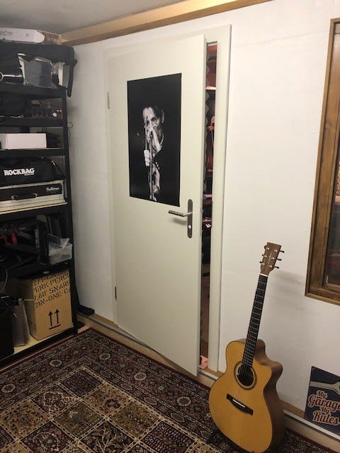
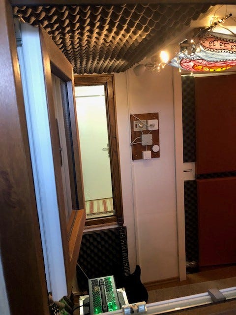
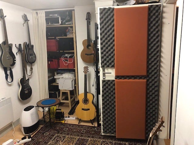
… and inside.
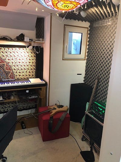

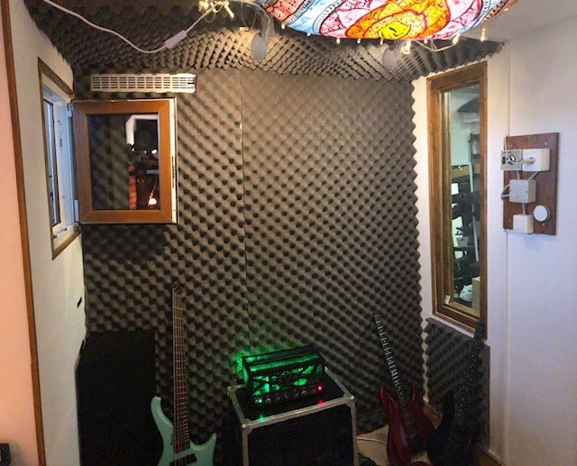
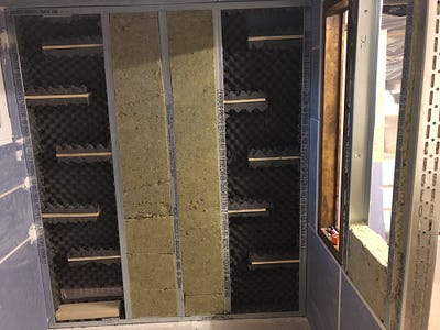
In case you want to know how to construct simple basstraps (as shown above and below in black in the corners), I recommend this article to you:
https://mark-evertz.medium.com/diy-basstraps-5e96bb24a8c3


Schreibe einen Kommentar
Du musst angemeldet sein, um einen Kommentar abzugeben.